[email protected]
+1 (502) 904-2126
One Westbrook Corporate Center, Suite 300, Westchester, IL 60154, USA
Site Map
 ISSN: 2574 -1241
ISSN: 2574 -1241
ISSN: 2574 -1241
Received: May 07, 2026; Published: June 18, 2026
*Corresponding author: César AC Sequeira, Materials Electrochemistry Group, Department of Chemical Engineering, Instituto Superior Técnico, Av. Rovisco Pais, Lisboa, Portugal
DOI: 10.26717/BJSTR.2026.65.010268
Unitized regenerative fuel cello (URFCs) for long-term. Energy storage has the potential to provide clean and sustainable solutions to grid and transportation applications. Here two of these devices, the proton exchange membrane URFC and the alkaline based URFC, are reviewed and shown to be performance-competitive with other long-duration on grid-scale energy storage technologies having promising future. Their main components, a hydrogen storage, an electrolyzes and a fuel cell, are discussed in terms of their application for hydrogen storage and for the oxygen reduction reaction and oxygen oxidation reaction at both electrolyser and fuel cells Parameters and issues involving the relevant electrochemical reactions occurring in these devices are present. In particular, a hydrogen storage unit is integrated into a UR-PEMFC by using activated carbon as the materials for the reversible and direct hydrogen electrode. This is complemented by hydrogen storage technologies, electrochemical storage of hydrogen, the proton flow battery concept, the components of a hydrogen system, the conventional hydrogen systems, and the integrated hydrogen storage in a UR-PEMFC. Combination of ORR and OER at the electrodes of URFCs are all sluggish compared to their hydrogen electrode counterparts from both a kinetic and mass transport perspective. This demands the study of the mechanism of oxygen reduction reaction in acidic electrolyte, the mechanism of oxygen reduction reaction in acidic electrolyte and possible advantages of alkaline electrolyte over acidic electrolyte. Transition metal oxides are adopted an electrocatalysts for the oxygen reactions, either as a support to enhance stability and activity of Pt, or as the direct catalysts for ORR/OER in alkaline media. Apart from referring their merits and demerits, different approaches to improve their catalytic activity such as the introduction of doping and defects, the manipulation of crystal facets, the engineering of supports, etc. Finally, this review demonstrates the viability of applying URFCs at elevated efficiencies and cast new light on electrode design and optimization of URFCs.
Keywords: Hydrogen Storage Electrode; Oxygen Electrocatalysts; Oxygen Evolution Reaction; Oxygen Reduction Reaction; System Design and Engineering; Transition Metal Oxides; Unitized Regenerative Fuel Cells
Abbreviations: URFC: Unitized Regenerative Fuel Cell; AC: Activated Carbon; ORR: Oxygen Reduction Reaction; PEMFC: Proton Exchange Membrane Fuel Cell; AEMFC: Anion Exchange Membrane Fuel Cell; OER: Oxygen Evolution Reaction; ZEV: Zero Emission Vehicle; HOR: Hydrogen Oxidation Reaction; PEMEC: Proton Exchange Membrane Electrolysis Cell; AFC: Alkaline Fuel Cells; AEMWE: Anion Rechange Membrane Water Electrolyzers; PEMWE: Proton Exchange Membrane Electrolyzers; DOE: Department of Energy; PEM: Proton Exchange Membrane; GDL: Gas Diffusion Layer; DFT: Density Functional Theory; AWE: Alkaline Water Electrolysis; RDS: Rate Determining Steps; CFSE: Crystal Field Stabilization Energy; NR: Nanocubes; OC: Octahedrons; ECSA: Electrochemical Surface Area; ITO: Tin-Doped Indium Oxide; NP: Nano Particles; GO: Graphene Oxides; RHE: Reversible Hydrogen Electrode; RDE: Rotating Disk Electrode; NCNT: Nitrogen Doped CNT; N-rGO: N-Doped Reduced Graphene Oxide; FeNC: Fe-Nitrogen-Carbon; CoNC: Co-Nitrogen-Carbon; CNTs: Carbon Nanotubes; RGO: Reduces Graphene Oxide
The limited number of oil and gas resources and the irreversible environmental effects of using fossil fuels, such as global warming, require increasing the share of renewable energy sources, in particular solar and wind, to meet the increasing global energy demand. However, an inherent characteristic of most renewable energy sources is their variability and intermittency. Hence, effective and economic energy storage technologies are needed to allow continuous energy supply from renewables. Hydrogen has been proposed as a storage medium with wide applications in grid storage systems and vehicular storage systems.
A conventional zero-emission hydrogen energy storage system consists of an electrolyser, a hydrogen storage, and a fuel cell. The electrolyser produces hydrogen gas usually by splitting water with electricity that has been produced by photovoltaic cells. The produced hydrogen gas is then stored in a separate hydrogen storage unit, in form of compressed gas or liquid, or stored in solid state storage materials like metal hydrides. When the electricity demand is higher than the electricity production from photovoltaic cells, hydrogen can be extracted from the hydrogen storage unit and transferred to a separate fuel cell. In the fuel cell, hydrogen and oxygen are recombined together to produce electricity and water. A more compact hydrogen system uses a unitized regenerative fuel cell (URFC) that is a single device that is capable to operate as fuel cell and electrolyser. With this device the hydrogen system needs only a URFC and a separate hydrogen storage unit. Hydrogen gas is produced in the URF during electrolyser mode. The produced hydrogen gas is stored in the hydrogen storage unit. When it is required, hydrogen is extracted from the hydrogen storage unit and goes back to the URF to react with oxygen gas during the fuel cell mode of the URFC.
The new concept is being studied in this paper, called a proton flow battery, is to integrate all the three components of a conventional hydrogen system, i.e. electrolyser, storage unit, and fuel cell, into a single device. In this concept, the hydrogen storage unit can be integrated into a proton exchange membrane URFC (or UR-PEMFC). The hydrogen ions (protons) are produced in the electrolyser mode on the oxygen electrode. The protons are transferred through the proton exchange membrane to the hydrogen electrode. The material of the hydrogen electrode is selected to reversibly store hydrogen. In these systems, Pt and a number of composite materials of activated carbon and nafion have been used for fabrication of the hydrogen electrode. Nafion is a proton conducting polymer and is used in this study to facilitate the proton distribution and transport into the composite electrodes. The protons combine with electrons on the hydrogen electrode and electrochemically are stored in the hydrogen electrode. In the fuel cell mode, hydrogen is extracted from the hydrogen electrode in form of protons. The protons are transferred back to the oxygen electrode, where they react with oxygen and produce electricity and water.
One aim of this study is to investigate the feasibility of using activated carbon (aC) as a hydrogen storage material in realisation of the concept of integrating hydrogen storage unit in a UR-PEMFC. To achieve this aim, a set of in-house activated carbons are fabricated and a number of composite materials from the activated carbon and nafion are made, and in general the physical and electrochemical properties of the composite materials are determined at different relative humidities. The composite materials are scaled up to fabricate composite electrodes. These composite electrodes are tested in a specially designed UR-PEMFC. To investigate the feasibility of the proton flow battery concept.
To address this question of the reversible and direct hydrogen storage, the following topics are analysed:- The hydrogen storage electrode, including the role of hydrogen in a sustainable energy strategy, hydrogen storage technologies, electrochemical storage of hydrogen and the proton flow battery concept; the concept of a regenerative URFC with an integrated hydrogen storage electrode, including the component of a hydrogen system, the conventional hydrogen system, and the integrated hydrogen storage in a UR-PEMFC. As reported above, apart from the hydrogen storage unit, the URFC integrates two more components, fuel cell and electrolyser.
Fuel cells and electrolysers have been attracting significant interest for energy applications for the past several decades as energy conversion and storage devices, respectively. The combination of both, known as the URFC had the highest energy density among all aircraft energy storage devices back in the 1990s (including supercapacitors, various chemical batteries, etc.) of about 450 wat-hours per kilogram. Advances in the two last decade have increased this number to 800 watt-hours per kilogram [1,2], and URFCs remain one of the highest energy density storage devices in aircraft today. In all off the above systems, the oxygen electrode limits the device performance. The oxygen reduction reaction (ORR) occurring at the proton exchange membrane fuel cell (PEMFC) and anion exchange membrane fuel cell (AEMFC) cathode and combination of ORR and the oxygen evolution reaction (OER) at the electrodes of URFCs are all sluggish compared to their hydrogen electrode counterparts from both a kinetic and mass transport perspective. The poor oxygen kinetics demand the development of electrocatalysts that enable the ORR/OER to happen at potentials close to their thermodynamic limit; this remains the major bottleneck for applicable devices [3]. Accordingly, Kinetic mechanisms of oxygen reduction and evolution reactions in several conducting electrolytes and at different operating temperatures are Key topics that deserve consideration. In fact, URFCs can be classified into high-temperature unitized regenerative solid-oxide fuel cells [4], intermediate temperature unitized regenerative protonic-ceramic fuel cells [5], low-temperature unitized regenerative hydroxide-exchange membrane fuel cells [6] and low-temperature proton exchange membrane unitized regenerative fuel cells, [7], which are the most promising. Compared to high temperature (600-900 °C) or intermediate temperature (500-600 °C) URFCs, UR-PEMFCs operate under mild reaction conditions, i.e. 20 to 100 °C moderate pressure, which could avoid mechanical and chemical compatibility issues for main cell components [8]. Furthermore, UR-PEMFCs can rapidly start-up/shutdown and load follows [9], giving more flexibility in terms of practical operation for grid balancing. Being impossible to deal with all these devices, here we are essentially concerned with PEM and alkaline devices [6,7]. It follows that the following topics are analysed: Oxygen electrocatalytic reactions, that includes the mechanism of oxygen reduction reaction in acidic electrolyte, the mechanism of oxygen evolution reaction in acidic electrolyte and the possible advantages of alkaline electrolyte over acidic electrolyte.
As reported above, the electrochemical reactions occurring at oxygen electrodes as the ORR/DER have very slow Kinetics, which has limited the industrialization of both fuel cels and electrolysers because loco Kinetics leads directly to high reaction overpotentials. Transition and other metal oxides have been widely adopted in terms of electrocatalysts for these oxygen reactions, either as a support to enhance the stability on activity of platinum, or as the direct catalysts for ORR and OER in alkaline media. However, what is not known is how and why metal oxides as support materials can influence the performance of precious metals through their interactions, what the active sites are for different electrochemical reactions and how to control the desired phases by manipulating the synthesis conditions. Cleary, these very important questions require appropriate consideration. In other words, apart from providing a background into the ORR/ OER mechanism, it is necessary to review and discuss metal oxides as catalysts and support materials for precious metals during aqueous oxygen reactions along with an understanding of the impact of metal oxide anchoring sites and synthesis parameters on catalytic activity, and durability, thus providing novel perspectives for the design of future advanced electrocatalysts. In summary, and considering our spacetime limitations, this review also studies: Overview of transition metal oxide electrocatalysts, including requirements of optimal catalysts, ORR/DER bifunctional electrocatalysts for UR-AFCs, requirements of optimal catalyst supports and impact of the support on ORR electrocatalysts; advancements of transition metal oxides, including Ni, Co, Fe, and Mn monometallic oxides, copper oxides, molybdenum oxides, bimetallic oxides of NiCo, CoFe, NiFe and MnCo, layered double hydroxides, metal sulfides, selenides, nitrides and carbides; cobalt- based find oxide as candidalis of ORR/DER reversible electrocatalysts in alkaline electrolyte, including spinel cobaltite oxides, nickel cobalt oxide and lithium cobalt oxide; advanced carbon-based hybrid material as candidates for reversible ORR/OER electrocatalysts in alkaline media, including in-situ and ex-situ synthesis processes, treatment of advanced carbon materials, hydrolysis in alcohol-water system/hydrothermal reaction, and chemical (Polyd) reduction process; highly durable and active cobalt oxide nanocrystals supported on carbon nanotubes as bifunctional electro catalysts in alkaline media, including objectives, results and discussion and a brief summary; approaches to enhancing the catalytic activity, including doping and defects, characterization of anion and action vacancies, support engineering considering Tiox, WOx, CeOx, and NiFeOx supports; facet, morphology and composition engineering; and in-situ iridium oxide electrochemically active surface area. A final section, preceding the references, reports conclusions and perspectives.
Role of Hydrogen in a Sustainable Energy Strategy
The problems with an energy economy based on fossil fuels can be classified into two categories. Firstly, there is the rising cost of fossil fuels, particularly oil and natural gas, and alarming concerns for scarcity of fossil fuel sources [10]. Secondly, there are the environmental issues of using fossil fuels, in particular emission of greenhouse gases, in unprecedented amount, leading to irreversible global warming [11-15]. An alternative source to meet the global energy demand, and avoid the environmental problems is to use renewable energy, in particular solar and wind energy. Electricity produced by photovoltaic panels and wind turbines has the potential to meet a major share of the total global demand [16]. However, an inherent characteristic of most renewable energy sources is their variability and intermittency [17]. Hence, an effective and economic energy storage technology is needed to allow continuous energy supply from renewables [18]. One solution is to use hydrogen as the storage medium [19]. The hydrogen economy has been described as a way to permit unrestricted economic growth with supplying an abundant source of energy in form of hydrogen while eliminating harmful environmental disadvantage of fossil fuels economy [20]. In this ideal economy, all energy needs would be met from hydrogen, produced from renewables, fossil fuels or nuclear fission power.
One of main drivers towards a hydrogen economy was the introduction of the Californian zero emission vehicle (ZEV) law in early 1990s. This law required US automakers to produce and sell a limited number of ZEV cars starting from 1998. At the time of introducing the law, Battery electric cars were considered to be the only feasible option to meet the requirements for a zero-emission automobile [20]. The separate collaborations between the Canadian firm Ballard Power Systems and two major car companies, Daimler-Benz and Chrysler in developing fuel cell cars led to switch the view of car of the future’ from battery powered to fuel cell powered [20]. The number of fuel cell prototypes jumped from 1.5 prototype annually to 20.2 between 1996 and 1999 [20]. USA and Iceland, that interestingly enough refused to sign Kyoto Protocol, were the main supporters for the new technology.
Interest in hydrogen economy and fuel cell intensified by President Bush’s State of the Union address in which he described commercialising fuel cell cars as a national commitment: [20]. The interest in hydrogen related research took off, as could be seen from the increased number of journal publications in the followed decade. The International Journal of Hydrogen Energy was founded by T. Nejat Vaziroglu, professor of University of Miami, in 1974. It is one of most prestigious periodicals in the field of hydrogen-related science with an impact factor of 8.1 (Elsevier website 2015). In 2012, the journal published 24 issues and 19 426 pages, as compared to 12 issues and about 1 230 pages in 2000 [ 21]. Over 2006 - 2012 the US government to some extent lost its interest in Bush’s vision of hydrogen economy, and at the same time US car manufacturers concluded that, at least in short term, fuel cell technology was not a cost-effective alternative to the battery technology [20]. An economic analysis examined the macroeconomic effects of fuel cell vehicles on California’s economy over the period of 2010-2030, taking into account the projected number of fuel cell cars, transportation energy consumption, and fossil fuel savings [22]. Wang [22] concluded that even in the most optimistic scenario, hydrogen vehicles would only make up a minor fraction of the on-road fleet in the future of California. Moreover, both moderate and aggressive scenarios have a slightly negative effect on California’s economy [22].
However, in recent years, a new wave of interest has appeared in hydrogen-related technologies around the globe. European countries are the new major supporters of hydrogen related technologies, with several R&D programmes have been launched and research-funding opportunities have been allocated to this field [20,23]. The Chinese government also has made huge investments in hydrogen related technologies, in particular fuel cell powered cars [24], China’s ambition to become an innovation-oriented nation by 2020 required heavy investment in science and technology including developing hydrogen fuel cell technology. Shanghai Tongji University is leading the fuel cell car project while Tsinghua University is working on fuel cell powered bus [25]. Furthermore, the State Council of China has listed hydrogen fuel cell vehicles on the list of vehicle-types to be supported in a New-Energy Vehicle Industry Developing Plan for 2012-2020 [26].
The Intergovernmental Panel on Climate Change included an important role for fuel cell vehicles in its global energy strategies relying greatly on renewable energy sources in order to meet 2050 greenhouse gas reduction targets [13] This report considered the technology of hydrogen fuel cell vehicles a true zero emission technology with hydrogen produced by electrolysis using wind (or solar) electricity, and electric vehicles charged from zero-carbon grid electricity [13]. Although, the time for exclusive hydrogen economy has passed, hydrogen fuel cell vehicles can still play a role where medium and long distance trips are required [19]. In this new vision, a hierarchy of spatially-distributed hydrogen production, storage and distribution centres would be created. These local centres rely on local renewable energy sources such as wind, solar and geothermal. The locally production, storage and consumption of hydrogen minimise the need for hydrogen pipelines. The required hydrogen pipeline system would be limited to link separate distribution networks for the main metropolitan areas and regions [19].
Hydrogen Storage Technologies
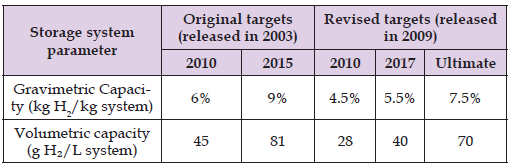
Progress towards a sustainable hydrogen economy has two main bottlenecks: hydrogen distribution and hydrogen storage. If 40 million hydrogen-powered cars are to be used in Europe by 2030, $8-33b is needed to build about 19 000 hydrogen fuel stations [27]. Even if the distribution challenge is solved, on-board hydrogen storage imposes a greater technical difficulty [28]. Table 1 shows the US Department of Energy’s (DOE) original and revised targets for on-board hydrogen storage for light-duty vehicles [29,30]. A comparison between the original targets and the revised target shows the difficulty in increasing hydrogen storage. The DOE’s targets are for the system of storage. A system includes a storage material, a storage tank, a heat exchanger, manifolds, regulators, valves and safety devices [31]. The most mature technologies, like compressed hydrogen gas in vehicles, are still far below the targets. For example, Honda FCX has a volumetric capacity of 23.9 g H2/L and Honda Clarity 2009 has a volumetric capacity of 22.9 g H₂/L [32]. There are three main methods for storing hydrogen [30,33-35]. Firstly, in physical storage, hydrogen is either stored as pressurised gas or cryogenic liquid. The second method is sorption that can store hydrogen either by physisorption or chemisorption in solid-state hosts. The third method is chemical storage by converting hydrogen to methanol or other chemicals. Compressed hydrogen and liquefied hydrogen are the most mature techniques in storing hydrogen and are discussed here in more details.
Table 1: DOED targets for on-board hydrogen storage for light-duty vehicles.
Many of the car manufacturers use 70 MPa as their technology of choice in on-board hydrogen storage [36]. Honda and Nissan use 35 MPa [37]. Hydrogen is a non-ideal gas and deviates from ideal gas behaviour at pressures higher than 35 MPa and shows volume higher than expected [38]. Round-trip efficiency for this method of hydrogen storage is about 87% for 80 MPa [39]. In other words, 13% of the energy content of the stored hydrogen is used to compress the gas. Liquefying of hydrogen occurs at 20 K, and so imposes the practical problems of preventing heat transfer from ambient environment, i.e. room temperature. The heat exchange between an environment at 300 K and hydrogen tank at 20 K leads to partial evaporation of the liquid hydrogen and pressure-increase inside the tank. When the pressure reaches a maximum level (in order of 1 MPa), hydrogen gas needs to be vented. The vented hydrogen is called boil-off gas [33]. Moreover, an energy equivalent of about 30% of the stored energy has been already used to liquefy the hydrogen gas [35]. Round trip efficiency for this method of hydrogen storage is about 70% [39]. Adsorption is the borderline between physical and chemical storage. There has been considerable interest over many years in storing hydrogen in solid-state hydride form [40]. This method of storage can be further divided into two groups: physisorption and chemisorption. Usually, the energy of adsorption is used to discriminate between chemisorption and physisorption [28,41]. The physical adsorption is caused by weak van der Waals forces between the gas and the surface of the host. The attraction between the gas and the surface is because of the fluctuations in the charge distribution of the gas molecules and of the atoms on the surface. The attraction between the gas molecules and the surface and the repulsion between the two that is resulted from their electron clouds, results a shallow minimum in the potential energy between 1 to 10 kJ mol-¹ [28]. Chemisorption is the creation of covalent bonds between the gas molecule and the surface atoms. The enthalpy of chemisorption (order of magnitude of 100 kJ mol- ¹) is higher than physisorption, but lower than an average chemical bond. Without spectroscopic techniques, it is very difficult to distinguish between strong physisorption and chemisorption [28]. Hydrogen uptake appears to be proportional to the surface area and porosity of the adsorbent [38]. When hydrogen atoms bond with another material, the hydrogen atoms can get even closer to each other than in compressed or liquid forms. That is the reason for potentially higher storage capacities in hydrides compared where chemical bonds are formed compared to physisorption, where only weak bonds are formed between hydrogen molecules and the surface of a material.
Electrochemical Storage of Hydrogen
In the electrochemical storage of hydrogen, hydrogen is directly stored in an electrode during electrolysis [42,43]. This method has been used in nickel-metal hydride accumulators [42]. By diffusing highly reactive protons directly into the solid storage material, it is possible that bonding reactions can be encouraged with materials with a high potential for storing hydrogen [44]. The key requirements of the storage medium for a successful wide application of hydrogen- related technologies are safety, low maintenance, stability and low cost. All the conventional storage methods, such as compression, liquefaction, or usage of metal hydrides fail to achieve at least one of the requirements [45]. Metal hydrides have been used in electrochemical storage of hydrogen, but they are heavy, expensive and not stable [42]. Moreover, their reversible capacity hydrogen storage is only about 2 wt% [46]. Carbon is a cheap and widely available material that is more environmentally friendly than metal [44]. The initial claims of Dillon, et al. [47] sparked great interest in the usage of carbon nanotubes in storing hydrogen, although their result has never confirmed by others. It is suggested that it is highly unlikely that carbon nanotubes can store a significant amount of hydrogen with hydrogen ingress in the form of gas [43]. In reviewing the data on hydrogen storage in single wall carbon nanotubes, Jurewicz, et al. [45] noticed that there is no systematic relationship between the indicated purity and the maximum discharge capacity. They concluded that the hydrogen storage in these studies occurs in other forms of carbon other than SWCNT [45]. In any method of preparation, besides the nanotubes, the material always contains other forms of carbon, in particular disordered carbon [45]. Jurewicz et al. have focused their efforts on activated carbon. Activated carbon is a porous carbon with high surface area. Activated carbon has a good thermal and electrical conductivity. It is also chemically stable and present relatively low cost and easy processability [43,48]. In the electrochemical storage, hydrogen penetrates into the pores of the activated carbon where it can be adsorbed due to the driving force of the negative polarization [46]. The pores smaller than 0.7 nm have been identified as the hydrogen storage sites in the activated carbon [43,44,46,49,50]. The state of the hydrogen in the activated carbon is in its atomic form [51]. The values of hydrogen storage in activated carbon have been reported from 0.95 wt% to 2.17 wt% [43,48].
The Proton Flow Battery Concept
The conventional hydrogen system that we are simulating here, consists of an electrolyser, a storage device for hydrogen and a fuel cell. The electrolyser produces hydrogen gas usually by splitting water with DC current. When the electricity demand is higher than the electricity production, hydrogen and oxygen can recombine together in a fuel cell. After hydrogen is produced by the electrolyser, it needs to be stored. In compressed hydrogen storage in a conventional hydrogen system, hydrogen is compressed to 35 or 70 MPa and stored in a high-pressure cylinder. A fuel cell is used to produce electricity from the hydrogen gas. Conversion efficiencies at the various stages in the process show that losses in producing and storing the hydrogen gas and then reconverting this gas back into electricity in a fuel cell reduce the roundtrip energy efficiency to be under 50% [52]. In the new concept that has been hypothesized here, a carbon-based hydrogen storage electrode has been integrated into a single proton exchange membrane (PEM) cell that could operate both as an electrolyser to split water and as a fuel cell to generate electricity. This single devise is capable of generating hydrogen, storing hydrogen and regenerate electricity by using the stored hydrogen. The potential device can be useful for a URFC. Production of protons for storage can be useful for continue for as long as water is being supplied and of course, as long as the protons can be accommodated in the storage electrode, hence the concept can be named “proton flow battery”. In charge mode, water splits on the left electrode (oxygen electrode). Oxygen gas escapes the electrode. Hydrogen ions (protons) go through the membrane to the other electrode due to the potential difference. On the right electrode (hydrogen electrode), protons react with electrons and atoms of the hydrogen-storage electrode to form a hydride. Determining whether this is a physisorption or chemisorption is beyond the scope of this discussion.
In discharge mode, the hydrogen ions are liberated from the hydrogen storage material by applying an electric load. The protons go through the membrane from the hydrogen electrode to the oxygen electrode. On the oxygen electrode, protons, electrons and oxygen atoms react together. The by-product of the reaction is water that is removed from the oxygen electrode. The proton flow battery cuts out many steps in the conventional process that incur energy losses. Hence, there is the potential for an overall higher roundtrip energy efficiency. In the concept, the avoided steps include conversion of protons produced during electrolysis into hydrogen gas, the compression of this gas, and subsequently the splitting of gas molecules in the fuel cell to release protons once again and generate electricity. In these terms it can be appropriate to investigate the technical feasibility of the proton flow battery in directly storing protons produced by electrolysis in a carbon-based electrode and recover the protons in fuel cell mode. A more detailed description of the concept is provided in the following section. This potential device inherits some of the advantages of batteries, like small size, safety, and a single unit with electricity in and electricity out, as well as retaining the advantages of a conventional hydrogen storage system, such as long-term energy storage time and high energy density. It also promises to be a cheaper device compared to common batteries by using carbon-based electrodes. Moreover, end-of-life recycling of this device produces fewer toxic materials compared to recycling batteries.
Components of a Hydrogen System
PEM Electrolyzers: The procedure of using electricity to decompose water into its constituent elements was first described by Anthony Carlisle and William Nicholson in 1800 [53]. They connected two conducting wires to two poles of a Volta battery and immersed the wires in salt water. Gas formation was observed around the wires [54]. Some historians credit Troostwijk and Diemann for discovering the effect in 1789 [55]. The proton exchange membrane (PEM) electrolyser is so-called because of using a polymer membrane as the electrolyte that is capable of conducting protons [56]. PEM electrolyzers can operate at current densities up to three times higher than their alkaline counterparts [57,58]. The higher current density may compensate for the higher cost of PEM electrolyser compared to alkaline electrolysers [59]. The solid electrolyte can be much thinner than an alkaline electrolyte and so the PEM electrolyser can be smaller and lighter than alkaline electrolysers [58,60]. Further advantages of PEM electrolysers are the ability to cope with transient electrical power variations and the potential to compress hydrogen at a higher pressure within the unit and with higher safety level [61].
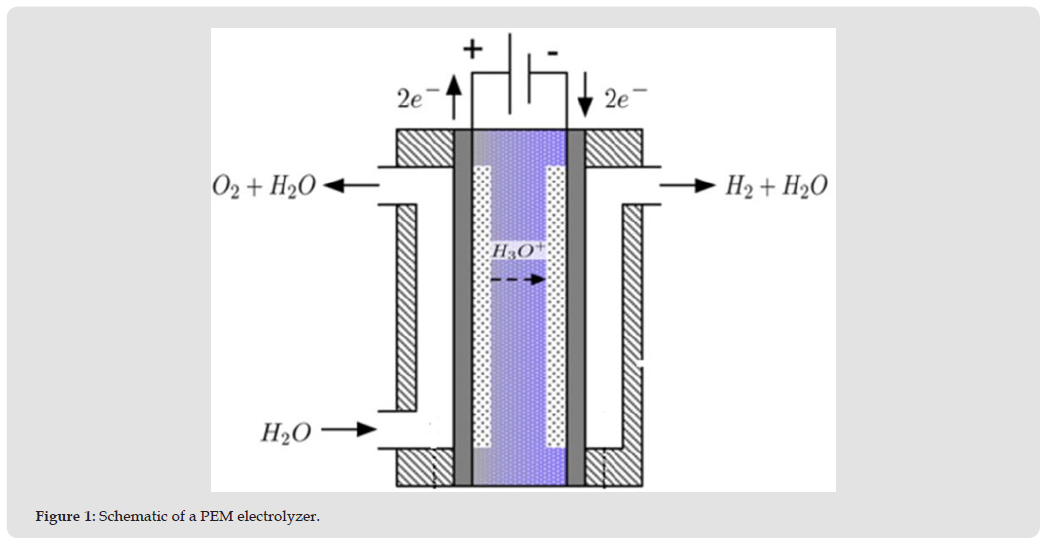
The water travels via channels in the oxygen side end-plate and gets distributed over the gas diffusion layer (GDL). Water diffuses into the GDL and reaches the catalyst layer where the water molecules are split into electrons, diatomic oxygen, and protons (H). The oxygen gas has to flow back through the catalyst layer and GDL to the flow channels and then out of the cell. The electrons travel from the catalytic layer, through the GDL, to the end-plate. The protons leave the oxygen side catalytic layer and are transferred through the solid membrane and reach the catalyst layer on the hydrogen side. There the protons combine with electrons and form hydrogen gas. The hydrogen gas then has to go through the GDL to the flow channels of the hydrogen side end-plate and leaves the cell. A schematic of a PEM electrolyser is presented in Figure 1.
Figure 1
The chemical reaction in the cell is [57]:

In the hydrogen side, the reaction is:
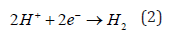
The overall reaction at the PEM electrolyser is

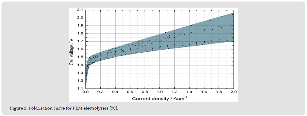
Figure 2 shows the state-of-the-art performance of PEM electrolysers from 2010 to 2012 for a range of publications with IR and Pt as catalysts [58]. It can be used as a benchmark to compare with order electrolysis methods. The reader is referred to a comprehensive review written by Carmo, et al. [58] for more details of the performance of over 80 PEM electrolysers.
Figure 2
Methods of Hydrogen Storage.
a. High-Pressure Hydrogen Storage
Compressed hydrogen storage refers to storing hydrogen gas in a pressure vessel at elevated pressure [62]. Three main pathways exist for compressing hydrogen [63]. In the first method, hydrogen gas is produced under ambient pressure and then is compressed by a multistage compressor. The second method uses pressurised water in high-pressure electrolysis. In the third method, hydrogen is produced under ambient pressure but does not leave the cell. The production of hydrogen is continued and accumulated hydrogen gas increases the pressure. Once the pressure is reached to a desired value, a valve opens and the compressed hydrogen gas escapes the cell and is stored in a high-pressure cylinder. The latter method is limited by the ability of a membrane to withstand the resulting mechanical stresses because of the pressure difference between oxygen side and hydrogen side [63]. In the present hydrogen fuel cell cars developed by the car manufacturing industry, typically pressure of 35 MPa and 70 MPa are being used [36,37]. Storing 1 kg of hydrogen at atmospheric pressure and room temperature requires 12.3 m³. Storing 1 kg of hydrogen gas at 35 MPa reduces this volume by 99.6% [64]. Hydrogen can be compressed by a piston-type compressor, although modification should be applied to the compressor because of the higher diffusivity of hydrogen compared to air [28]. For two reasons, pressures higher than 70 MPa are not sought after. Firstly, the hydrogen gas diverts from ideal gas behaviour and more work has to be done to get to the higher pressure [38]. Secondly, higher pressure requires higher strength of the high-pressure cylinders. This usually means thicker walls and heavier cylinder. The combination of these two facts leads to ultimately lower gravimetric hydrogen density at very high pressures [28].
High-pressure storage is currently the cheapest solution to store hydrogen and in particular attractive for fuelling stations [65]. Another advantage is the short refill time of the tanks. An empty tank can be filled with 5 kg of hydrogen within three minutes [38]. The major limitation of high-pressure storage of hydrogen is still the relatively low volumetric density [65]. The volumetric density only goes up to 39.5 for kg/m3 for 70 MPa [66]. The volumetric density of petrol is 740 kg/m3 [67]. The volumetric energy density of hydrogen gas is about one third of the volume energy density of natural gas ate the same pressure [28]. The other issue in on-board storage is the shape of the pressure vessel. A large amount of space has to be allocated in the car to fit a cylindrical shape vessel [65]. Other shapes lead to lower gravimetric hydrogen density [65]. Another issue is concerns about safety in vehicles and populated areas [28].
b. Liquid Hydrogen
Hydrogen becomes liquid at temperature below 21.2 K at atmospheric pressure [28]. The simplest liquefaction cycle is the Joule-Thompson cycle. There are two major challenges in storing hydrogen in liquid form. The first issue is the large amount of energy that is required for cooling hydrogen gas to 21 K. The energy required for liquefying hydrogen is about 30% of the lower heating value of the stored hydrogen [65]. The second issue is the thermal insulation of the cryogenic vessel and heat transfer to the environment [68]. Thermal conduction into the vessel happens through its surface, cables and fixtures [65]. Thermal radiation also contributes to heat transfer to the vessel [38]. The transferred heat to the vessel causes evaporation of hydrogen. The evaporated hydrogen increases the pressure inside the vessel and before the pressure goes above allowed limit the gas should be vented. The part of hydrogen that is vented is called boil-off gas and happens after a period of time that is called dormancy [64]. Boil-off volume is a function of size, shape and thermal insulation of the vessel [28]. The boil off issue imposes a major safety issue for the vehicles left for few days in a closed space like a garage [65,69]. The vessel within vessel construction may reduce the rate of boil off losses an increases safety even in sudden rapture of the inner vessel [66]. A problem with using liquid hydrogen in fuel stations is that the entire transfer line from the station’s hydrogen reservoir to the car tank needs to be cooled down to 21K [38] Pressure cryogenic tanks that can work at cryogenic temperatures and high pressures are the next generation of vehicular storage systems that have been developed in [70].
c. Hydrogen Sorption in Solid State
The two types of sorption of hydrogen in solid materials are chemisorption and physisorption. The physisorption is depends on weak van der Waals attraction between the host material and molecular hydrogen. Chemisorption is the much stronger chemical bonding between the host material and atomic hydrogen [71]. Chemisorption is due to formation of covalent bonds between carbon and host material [72]. Sorption is considered to be the borderline situation between weak bonds of physical storage and strong bonds of chemical storage [38]. Metal hydrides are examples of chemisorption and activated carbon is an example of both chemisorption and physisorption. Typical metal hydrides are in the form of AB5 and AB2 where A is typically a rare earth metal that tends to form a stable hydride and B is often a transition metal that forms unstable hydrides [68]. There are two types of metal hydrides. The crystal structure of an interstitial hydride like LaNi5 does not change upon insertion of hydrogen. The other type of metal hydrides, like MgH2, forms a new structure upon insertion of hydrogen and is called a structural hydride [71]. Materials with high surface area like metal-organic frameworks, carbon nanotubes and activated carbon are also good candidates for hydrogen adsorption [71].
The hydrogen storage capacity of metal hydride is limited to roughly 2 wt% [38]. The search to find new metal hydrides is ongoing [35]. Hydrogen storage in complex hydrides like the family of the borohydrides, e.g. Mg (BH4)2 or Na2 Zr (BH4)6, has ignited interest in research in this family [31]. Although these materials have high hydrogen storage density, e.g. NaBH4 (10.8wt%), NH3 BH3 (19.5 wt%), and N2H4 (12.5 wt%), the system-based storage density is much less than DOE targets [30,31,73]. Another key limitation of metal hydrides is the need for heat removal during charging [73]. Carbon materials have received exceptional attention as possible hydrogen storage materials because of low cost, availability, environmentally friendly recycling, low density, and good chemical stability [74]. A range of carbon materials have been proposed like carbon nanotubes, carbon nanofibers, and activated carbon [74]. Hydrogen storage in activated carbon seems to be more promising than in carbon nanotubes [68].
d. Chemically Bonded Hydrogen Storage Liquids
In chemical storage, hydrogen makes a strong covalent bond with the host material, like methanol [28]. The energy of the bonds is at least an order of magnitude higher than physisorption [28]. Some of the chemical storage materials are ammonia and methanol [35]. Ammonia is 18% hydrogen and is produced over an iron catalyst in the Haber-Bosch process. Although ammonia is a gas, it can be easily liquefied. Although liquid ammonia can be catalycally decomposed at 400°C, it is very corrosive [65]. The process of introducing hydrogen to the material and extracting hydrogen from it is called hydrogenation and dehydrogenation [38]. The hydrogenation is a complex process and needs to be done off-board [71]. Obtaining hydrogen from these components may also require some energy loses. Compared to the compressed, liquid and metal hydrides, this method of hydrogen is in its early stages of development [75]. The hydrogen is produced by a chemical reaction. The reaction products should be removed and recycled off-board [76].
PEM Fuel Cell: A fuel cell is an electrochemical cell that directly converts the chemical energy of reactants to electricity [40] Sir William Grove is credited with using electrolyser principles to electrochemically compose water by reassociating hydrogen and oxygen atoms in a fuel cell or as he named it, a gaseous voltaic battery [77,78]. Thomas Grubb and Leonard Niedrach from General Electric made the first PEM fuel cell for the Gemini Program in the early 1960s [79]. In early 1990s, a renewed interest in this field expanded fuel cell application to PEM fuel cell-powered submarines (made by Perry Energy System 1989), buses (made by Ballard Power System), and passenger cars (made by Perry Energy System1993). The operating temperatures of PEM fuel cells are between 50 and 100°C and their efficiency lies between 40-60% [40]. The advantages of PEM fuel cells are using a solid electrolyte, low operating temperature and quick start-up [40]. In a PEM fuel cell, hydrogen gas is supplied from the storage system to the anode electrode and oxygen (or air) is supplied to the cathode [56]. At the hydrogen electrode (anode), hydrogen splits to hydrogen ions (protons) and electrons.
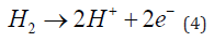
The protons go through the membrane to oxygen electrode (cathode) and electrons go through an external load and produce electric current. The protons, electrons and oxygen combine on the oxygen electrode and produce water.

Many car manufacturers are using PEM fuel cells as their technology of choice; Honda (FCX Clarity), General Motors (Chevrolet Equinox), Hyundai-Kia (Kia Borrego SUV), Volkswagen (Passat Lingyu), Toyota (FCHV-adv), and Nissan (Xterra FCV) [80]. A more detailed review of PEM fuel cells in automobile is available in [54].
Structure and Principles of A PEM URFC: The unitised regenerative fuel cell is a single device that is capable of functioning in either electrolyser mode or fuel cell mode [81]. In URFC the same cell is capable to split water to hydrogen and oxygen by using electricity in the electrolyser mode and also recombine oxygen and hydrogen to produce DC electricity in fuel cell mode [82]. The reaction of a PEM URFC is:

In electrolyser mode, the reaction moves in the forward direction and in fuel cell mode the reaction moves in the reverse direction. First, the URFC works as an electrolyser to produce hydrogen and oxygen which are stored in a separate storage unit. The hydrogen and oxygen are later supplied back to the same URFC that is now working as a fuel cell [81]. The difference between a URFC and a secondary battery is that the URFC needs an external storage system. The concept of a PEM URFC was introduced in early 1960s, mainly for space application [83]. Early promising results of PEM URFC were obtained at General Electric in 1972 when reversible operation was shown to be feasible without significant degradation of the cell membrane [84]. Today many companies like Lynntech Inc., Glenn Research Centre, Giner Inc., and Green Volt Power Corp are active in the field of PEM URFC technology [84]. NASA applications for PEM URFC include high altitude airships, lunar or Mars-based outposts and other applications instead of secondary battery where the discharge period is one to two hours long or longer [85]. There are two types of PEM URFC [86]. In ‘hydrogen and oxygen electrodes constant’, the electrode that evolves hydrogen in electrolyser mode is the same electrode that uses hydrogen in fuel cell mode. This concept was also called ‘hydrogen and oxygen electrodes in the literature [84]. This electrode is called the hydrogen electrode. Similarly, oxygen is evolved and used on a same electrode, which can be called the oxygen electrode. A schematic of this type of URFC is presented in Figure 3. In this type of PEM URFC, the catalyst layers on both electrodes need to be bifunctional. On the oxygen electrode, the catalyst should assist water splitting in electrolyser mode and encourage water formation in fuel cell mode. The catalysts on hydrogen electrode should encourage hydrogen formation in electrolyser mode and assist hydrogen splitting in fuel cell mode.
Figure 3
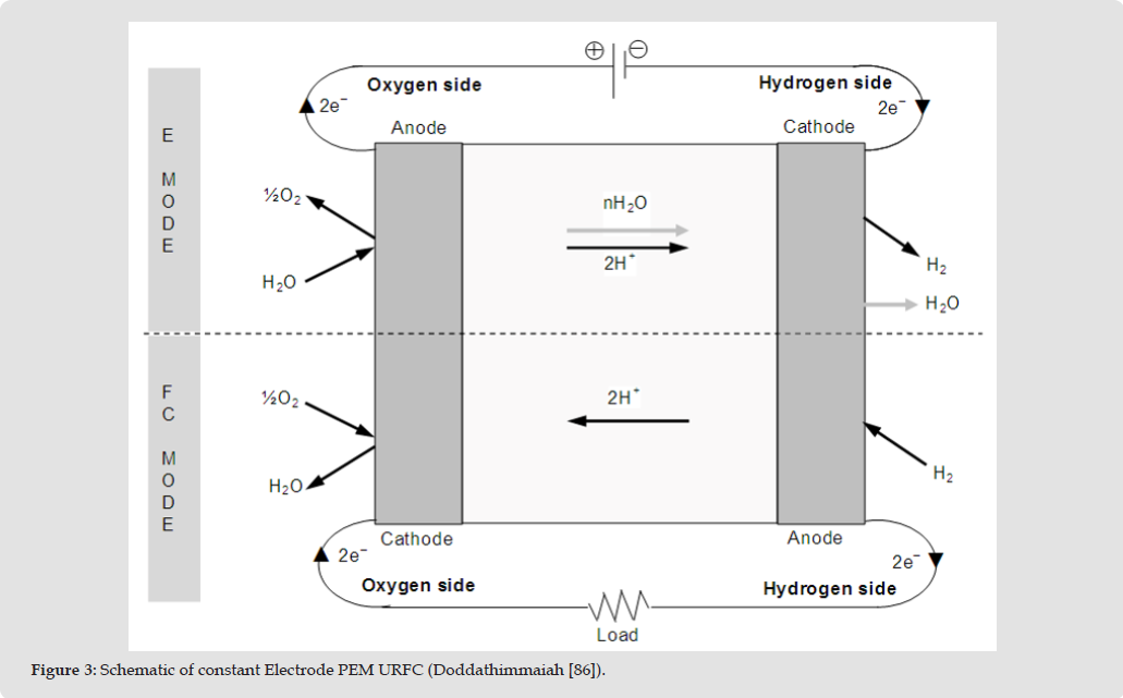
The major advantage of this type of PEM URFC is that hydrogen gas and oxygen gas are completely separated from each other and cannot mix. Another major advantage of this type is that water is introduced to and extracted from the same side and water management can be limited to only that side of the cell. The second type of PEM URFC is called ‘hydrogen and oxygen electrodes interchange or reduction and oxidation electrodes’ [84,86]. In this type, hydrogen (or oxygen) is produced on one electrode and consumed on the other electrode. The advantage of this type of URFC is that the need to use bifunctional catalysts is eliminated. First attempts to build a PEM URFC were made in 1960s, but it was only in 1972 that General Electric made a PEM URFC with good performance and acceptable lifetime [84]. A commercial PEM URFC was manufactured in 1992 by Proton Energy Systems that was able to produce 5 kW in fuel cell mode and 15 kW in electrolyser mode [84,87]. Suggest that titanium is a good choice for bipolar plates for a PEM URFC due to its high resistance to corrosion. Catalysts materials such as Ir, Ru and Pt have been found to produce the best results on the oxygen electrode in a PEM URFC [86,87]. The method of preparation of the above catalysts has also been found to affect performance [88]. PEM URFCs still require more study to optimise their electrochemical performance [83]. The performance of a PEM URFC may be very close to state-of-the-art dedicated electrolysers and fuel cells; for example, the PEM URFC that was developed in the GenHyPEM project showed an efficiency of 80% in electrolyser mode and a cell voltage of 0.8 V in fuel cell mode [83]. Even so, PEM URFCs suffer from short lifetime and their performance depreciated after only a few hundred cycles [83].
Conventional Hydrogen Systems
A Hydrogen System Employing an Electrolyzer, Storage Unit and Fuel Cell: A conventional hydrogen system includes an electrolyser, a hydrogen storage system, and a fuel cell. A schematic of the conventional hydrogen system is presented in Figure 4. The excess solar energy can be used to produce hydrogen via electrolysis of water. The hydrogen is stored and later used in a fuel cell to produce electricity when the electricity demand is higher than electricity supply [89]. Power supply for remote areas can be a niche market for such systems [86,89]. The electrolysis of water is one of the most developed methods of producing hydrogen in industries [90]. Among the technologies in water electrolysis, PEM electrolysers are very practical in producing high-quality hydrogen [90]. The main advantages are scalability and zero emission production [90]. A study in Algeria, showed that a 50 W PEM electrolyser connected to a PV module is estimated to produce between 20-29m3 of hydrogen, annually [91]. Another advantage of the hydrogen system over batteries is that batteries have a self- discharge tendency and so can only store energy for short periods of time [92]. The main disadvantage of the system is the number of devices in the system. The roundtrip energy efficiency when going from electricity in to electricity out - typically 40-45% via electrolyser, gas storage unit, and fuel cell - compared to batteries at 70-80% [52]. Another issue is the size of the system. A large volume needs to be allocated to the system and hence, diminish the prospect of using the system for mobile applications.
Figure 4
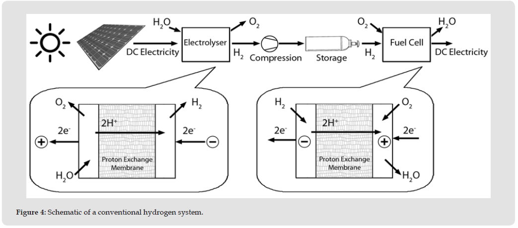
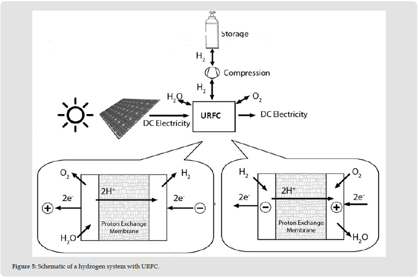
A Hydrogen System Employing a URFC and Storage Unit: It has been shown that a unitised regenerative fuel cell is a single device that can be used both as an electrolyser and fuel cell in different times. Since in the conventional hydrogen system, electrolyser and fuel cell never work simultaneously, these two devices can be replaced with a single URFC. In this hydrogen system, first the URFC works as an electrolyser and splits water into hydrogen and oxygen by using the excess electricity. The hydrogen is stored in a separate unit. When the electricity demand is higher than electricity production, the hydrogen is supplied from the storage unit to the URFC that now works as a fuel cell and combines hydrogen and oxygen and produce electricity [93]. The schematic of this hydrogen system is presented in Figure 5. This system has fewer devices compared to the conventional hydrogen system in the previous hydrogen system. The URFC should be compatible in efficiency and lifetime to a dedicated electrolyser and fuel cell [86]. From a financial viewpoint, by using a URFC, the purchase of a separate electrolyser and a separate fuel cell, both expensive items, can be avoided with purchase of a single cell at a lower cost [94]. The efficiency of the URFC, both in electrolyser mode and fuel cell mode, has been an interest for many research activities [81,86,95]. The performance of PEM URFCs can be very close to the state-of-the-art electrolysers and fuel cells, but URFCs suffer from short lifetime and their performance degrades significantly after few hundred cycles [83]. One of the issues related to the hydrogen system with URFC is that it still needs an external hydrogen storage unit. Present study seeks to overcome this shortcoming by integrating a hydrogen storage electrode into a PEM URFC.
Figure 5
Integrated Hydrogen Storage in a PEM URFC
The Concept of the Proton Flow Battery: In the proton flow battery concept to be investigated in the present project, a solid hydrogen storage electrode is integrated into a single proton exchange membrane (PEM) cell that can operate reversibly as an electrolyser to split water or as a fuel cell to generate electricity, that is, a unitised regenerative fuel cell (URFC) [86,95]. A schematic of the concept is shown in Figure 6. In electrolyser mode, water is split into hydrogen ions (that is protons, H+), electrons and oxygen gas, as shown in equation 7. The oxygen gas goes through the oxygen electrode and channel flows of the oxygen-side end-plate and leaves the cell. The electrons also leave the cell through an external circuit. The hydrogen ions go through the membrane to the hydrogen electrode:

Figure 6
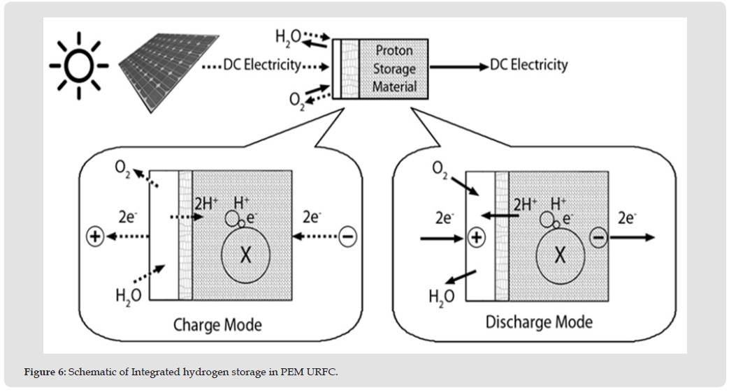
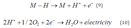
On the hydrogen electrode, that is, the hydrogen storage electrode, protons, emerging from the membrane enter the solid storage directly and then react with electrons and storage material atoms to form a hydride without producing hydrogen gas:

where M is the material of the hydrogen storage electrode. Production of protons for storage can continue for as long as water is being supplied, and of course as long as the protons can be accommodated in the storage electrode, hence the proposed concept has been called proton flow battery. The hydrogen can be stored in the electrode of the PEM URFC for a period of time. Hence, the hydrogen electrode of the proton flow battery acts as a storage unit. When there is a demand for electricity from the PEM URFC, the hydrogen ions would be liberated from the storage material like a secondary battery. The protons go through the membrane to the oxygen electrode and react with oxygen gas and electrons:
It can clearly be seen by comparing Figures 5 & 6 that the proton flow battery cuts out many steps in the conventional process that incur energy losses. Avoided steps include conversion of protons produced during electrolysis into hydrogen gas, the compression of this gas, and subsequently the splitting of gas molecules in the fuel cell to release protons once again and generate electricity.
Benefits and Potential Applications of a Proton Flow Battery: The proton flow battery can avoid the need for using an external hydrogen storage system in URFC hydrogen systems. The concept also only has one device and hence it is more compact compared to URFC hydrogen system and may be more suitable for mobile applications. By diffusing highly-reactive protons directly into the solid storage material, it is possible that bonding reactions can be encouraged with materials with a high potential for storing hydrogen but which cannot be made to react with hydrogen gas unless the pressure (and sometimes temperature too) is prohibitively high (for example, graphitic carbon, aluminium, and magnesium). Thus there is the possibility of storing hydrogen in relatively light and abundant materials (for example, graphitic carbon and aluminium), and hence achieve higher gravimetric and volumetric energy densities, and lower costs per unit mass of hydrogen stored, than presently available metal hydrides, which tend to be the heavier elements and often contain very costly rare earth elements as well. In the conventional process, protons must combine in pairs with electrons in the catalyst layer of a conventional PEM electrolyser to form hydrogen gas. This hydrogen must then be compressed, by continued production by the electrolyser so that the amount of hydrogen gas in a fixed volume container steadily increases, or by using an external compressor. In either case there is an energy penalty to accomplish the compression. Hence there is the potential for overall higher roundtrip energy efficiency (electricity to hydrogen to electricity) in the proton storage process.
Mechanism of ORR in Acidic Electrolyte
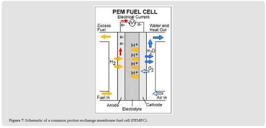
PEMFCs are the most widely applied and industrially mature fuel cells for mobile applications. A simplified schematic of a common PEMFC is shown in Figure 7 and the cell reactions are given as Equations 11-13. At the anode, hydrogen is electrochemically oxidized producing protons and electrons. The protons transfer through a proton-conducting polymer electrolyte (most commonly Dupont’s Nafion®) and meet with the protons and electrons, and oxygen, at the cathode side to produce water.
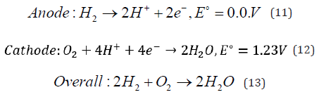
Figure 7
The electrochemical efficiency of a fuel cell can be calculated as a simple ratio of the cell operating voltage, Ecell in Equation 14 and the thermodynamic voltage, Erev [96].

The thermodynamic cell voltage, which depends on the partial pressures of the reactants and the cell temperature, is approximately 1.23 V under standard conditions (25 °C, 1 atm), according to Eq.11 and 12. The second term on the right side of Eq. 14 is the voltage loss in the cell due to ohmic resistance, including both the electronic contact resistance between fuel cell components and proton conduction resistance in the membrane [97]. The third term is the potential difference between the thermodynamic oxygen reduction reaction (ORR) potential and the experimentally observed potential, the socalled overpotential, which is due to the sluggish ORR kinetics. Note that the hydrogen oxidation reaction (HOR) kinetics at the anode is so rapid, that the HOR overpotential is not typically considered at all. The fourth term is the mass transfer loss, incurred by the poor oxygen- transport through the diffusion medium and the catalyst layer. Therefore, the ORR occurring at the cathode is the most challenging technical issue and most intensively investigated due to the sluggish kinetics and mass transport issue compared with the anode hydrogen oxidation reaction. There are two possible pathways for the ORR: a partial two-electron reduction to hydrogen peroxide (H2O2) or a full four-electron reduction to water Figure 8. In an operating PEMFC, the former is unwanted because not only does it clearly decrease the energy conversion efficiency, peroxides produce radicals that can attack and destroy the polymer electrolyte. Despite decades of development, state-of-the-art ORR catalysts are still platinum nanoparticles supported on carbon black (Pt/C). Density functional theory (DFT) calculations have shown that Pt (111) facets (and facets of Pt alloys) provide the ideal oxygen adsorption energy, a key descriptor for ORR activity. Oxygen adsorption is followed by either O2* dissociating into 20* to react with hydrogen forming water (four- electron route) or directly reacting with hydrogen producing water with (two-electron route) or without (four-electron route) forming intermediate of H2O2* [98]. Figure 9 The binding energy (associated with the d-band center) between oxygen atoms and the Pt catalyst surface not only help to enhance the electron transfer rate but also to facilitate breaking of the O=O bond [99-102] which allows an overwhelming amount of the reaction to occur through the preferred four-electron pathway.
Figure 8
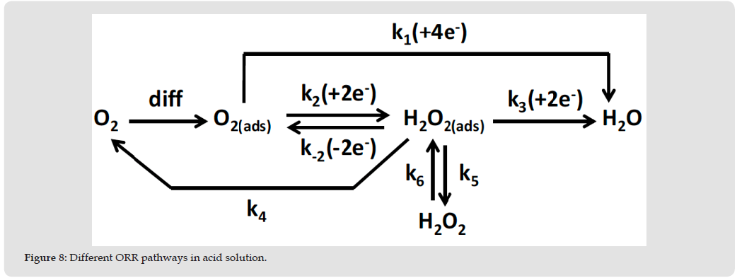
Figure 9
Mechanism of OER in Acidic Electrolyte
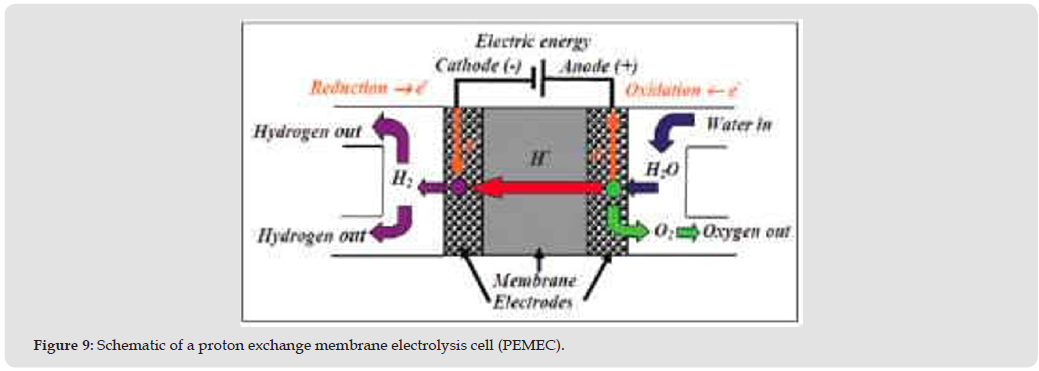
A schematic of the proton exchange membrane electrolysis cell (PEMEC) is shown in FA and cell reactions are given as Equations 15- 17:
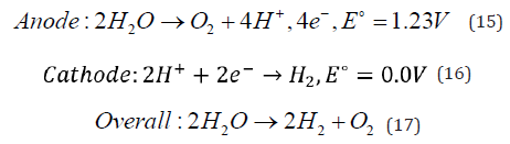
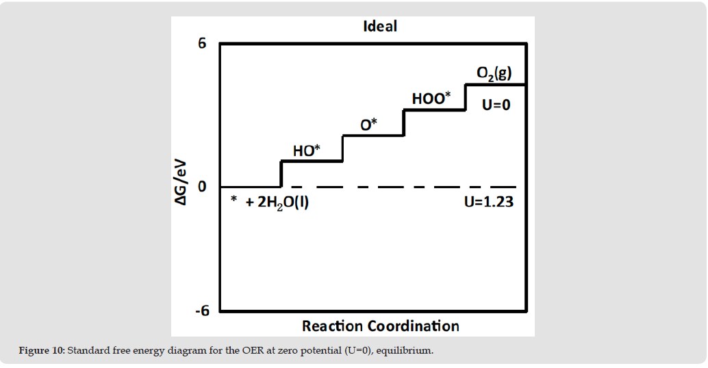
As an energy storage system, a PEMEC electrochemically oxidizes deionized water pumped into the anode of the electrolyzer, producing O2 as well as protons and electrons. Similar to the PEMFC, the protons transfer through the polymer membrane; however in the PEMEC, they combine directly with the electrons from the external circuit to produce pure hydrogen, which is basically a reverse mode of a fuel cell. When combined with renewable and intermittent energy like solar and wind, PEMECS can play an essential role by producing hydrogen with relatively high efficiency, and unlike steam reforming systems PEMECs also quickly cycle up and down, and deliver hydrogen with high and differential pressure (self-compression). However, there are several challenges that have to be solved in this process, with the most pressing being to reduce the OER overpotential, and hence energy losses, at the PEMEC anode [103]. Improving the anode catalyst will thus improve the efficiency of the electrolyzer and reducing the cost of the catalyst is also commercially desirable. Therefore, many studies focus on understanding the fundamental mechanism of the oxygen evolution reaction (OER). Some computational work has been done on several classes of materials including [104] and rutile oxides [105,106]. In these studies, researchers proposed that the OER metals mechanism consists of four consecutive proton and electron transfer steps, with the intermediates being HO*, O*, and HOO*. They predicted the OER activity with estimated O* binding energies as a descriptor, which mirrors work on ORR catalyst in fuel cells. Later, the Rossmeisl group introduced a new, universal descriptor for the OER a scaling relationship between the binding energy of HOO* and HO*, which was derived from first principles periodic DFT calculations [107]. The proposed free energy diagram for the four electron reaction pathway for an ideal catalyst is shown in Figure 10. They claimed that the free energy difference between the adsorbed oxy and hydroxyl anions (ΔGO∗ − ΔGHO∗) was the origin of the overpotential for oxygen evolution catalysis, which agreed well with experimental results in literature. Their studied oxides included rutile, perovskite, spinel, rock salt, and bixbyite oxides. The most commonly used and industrially mature electrocatalysts in PEM electrolyzers are noble metal oxides with a rutile crystal structure, ruthenium and iridium oxide. However, since dominant cost of an electrolyzer is electricity, about 70% of the total [108] increasing the efficiency is of a higher importance than decreasing catalyst cost. Efforts for developing a high activity and efficiency OER catalyst in acid have lasted for decades.
Figure 10
Possible Advantages of Alkaline Electrolyte Over Acidic Electrolyte
The study of electrocatalyst activity and stability in alkaline media was a popular research topic from the 1960s through the 1980s because of the development of alkaline fuel cells (AFCs) for space applications [109]. However, its terrestrial development was limited by problems with electrolyte carbonation and electrolyte leakage. Recent designs of AFCs such as laminar flow-based micro fuel cells, the boom of alkaline fuel cell companies such as AFC Energy and the breakthrough development of stable, high conductivity anion exchange membranes and ionomers have started to overcome the problems of conventional AFCs and revive researchers’ interest in electrochemical reactions in alkaline media [110-112]. In alkaline media, the ORR is reasonably more favourable from a kinetic perspective than it is in acidic solution because the metal surface tends to have fewer oxygenated adlayers, and the potential range of M-OH formation on platinum metals in alkaline solutions is considerably wider than in acidic solutions [113] The electrode reactions in the anion exchange membrane fuel cell (AEMFC) are shown in Equations 19-20. The oxygen reduction reaction (ORR), which occurs at the AEMFC cathode, is one of the most widely studied reactions to date, similarly for the alkaline OER reaction (shown in Equation 21 at the anode of anion exchange membrane electrolyzer cell (AEMEC). Generally, researchers have proposed that the ORR in alkaline media proceeds through multistep reactions involving first the formation of an HO2 - intermediate from adsorbed O2 on the active sites of the catalyst surface, followed by its further reduction or decomposition to OH- ions [114-115]
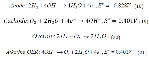
Though the shift in potential with pH is very well known (0.059V/ pH) and often discussed, the differences in the interface and its role in the ORR mechanism are not as well known or as widely discussed. First, the lower potential required for the ORR in alkaline media changes the surface free energy, weakening the Pt-O bond energy compared to acid electrolyte [116]. This decreased bond energy, combined with the outer- sphere electron transfer mechanism [117,118] decreases the overpotential for the ORR in alkaline media relative to acidic media. Simply put, the ORR in alkaline media is more facile than it is in acid. The lower energy requirement, combined with improved stability of transition metal systems in alkaline vs. acid media, suggest that the search for ORR/OER catalysts and support in alkaline media can expanded over much of the periodic table from noble metals to earth-abundant elements. The catalytic activity of the ORR electrocatalysis in alkaline media has been observed for elements over a significant portion of the periodic table from carbon compounds [119-121] to various transition metals [122-124] coinage metals [125-130], metal macrocycles including porphyrins [131-134] phthalocyanines [135-138] and metal oxides [139]. Although some high activity non-platinum group metal catalysts have been shown for the ORR in alkaline media [140,141], unfortunately, Pt-based catalysts still remain the most popular in the literature because of their proven combination of high stability and activity.
Although for the past few decades precious metal catalysts have been extensively investigated for fuel cell and water electrolyzer electrocatalysts [142-149], they still have very high cost and poor reversibility for relevant electrode reactions such as hydrogen and oxygen reactions. Section 5 of this work will shed light upon the development of non-precious metal oxides, either functional or bifunctional for HER and ORR/OER electrocatalysts for reversible anion rechange membrane water electrolyzers (AEMWE) and anion exchange membrane fuel cells on URFCs. Among these, AEMWE stands out by integrating the cost-effectiveness of alkaline water electrolysis (AWE) with the high performance and rapid response of proton exchange membrane electrolyzers (PEMWE), positioning it as an ideal candidate for largescale green hydrogen production in the future. A significant advantage of AEMWE is its compatibility with non-precious metal catalysts in alkaline environments, thereby markedly reducing catalyst costs. Unlike PEMWE, AEMWE obviates the need for precious metals such as platinum (Pt) and iridium (Ir), rendering it more economically viable for extensive applications [150]. Because the fields of REMWES and AEMFCs or URFCs only emerging more recently, it is necessary here to include a more in-depth discussion than the sections above where countless research and review articles have already been written about each topic.
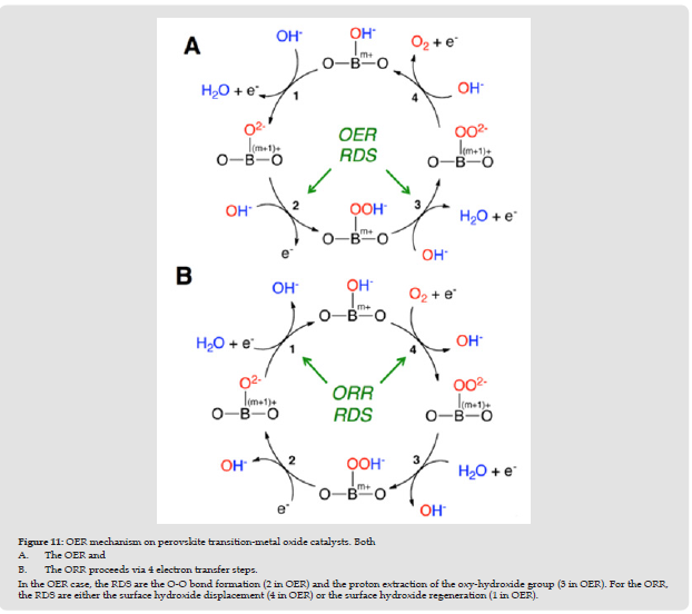
It is always challenging to find stable and efficient bifunctional electrocatalysts, which drive both oxygen reduction and evolution reactions, because good catalysts for ORR mostly result in poor performance for OER and vice versa. Take the ORR and OER mechanisms on perovskite oxides as an example. Both reactions proceed via 4 electron transfer steps (indicated by the black numbers inside both reaction circles) as proposed by Suntivich et al. in Figure 11 [151,152]. In the OER rate determining steps (RDS), a good OER catalyst tends to either lower the O-O bond formation energy (step 2 in the OER circle) or the proton extraction energy from the oxy-hydroxide group (step 3 in the OER circle). However, in the ORR case, the raised binding energy of O-O or the lowered binding energy of O-H would make the breakage of O-O and proton adsorption from water more difficult to occur in the reverse steps (steps 2 and 3 in the ORR circle). Similarly, what a good ORR catalyst may do in its RDS - either the surface hydroxide displacement (step 4 in the ORR circle) or the surface hydroxide regeneration (step 1 in the ORR circle) - would also result in the same situation to the reverse steps 4 and 1 in the OER circle. Therefore, it is always challenging to maintain a proper balance for reversible ORR/OER catalysis.
Figure 11
The most popular family of non-precious metal bifunctional OER/ ORR electrocatalysts in alkaline media is transition metal oxides such as perovskite (i.e. LaNiO3, LaCoO3) and spinel-type transition metal oxides (e.g. Co3O4 and NiCo2O4). The spinel structure possesses a general formulation A2+B3+2O2-4, with the oxide anions arranged in a cubic close-packed lattice and the cations A and B occupying some or all of the octahedral and tetrahedral interstitial sites in the lattice. A and B can be a single transition metal element with prototypical charges of +2 and +3, respectively, like aluminium, iron, cobalt, manganese, etc. A can also be a substitution, like copper, zinc, magnesium or nickel, of B. Spinel structures can be active for both ORR and OER reactions because they can provide donor-acceptor chemisorption sites for the reversible adsorption of oxygen because of the presence of mixed valences of the cations [153].
Though mixed valence oxides involving transition metals have been broadly considered as possible alternatives with ORR and OER catalytic activity in alkaline media, cobalt-based oxides (including their binary and ternary composites) in particular have shown generally high activity and relatively easy preparation, which has increased interest in these materials in recent years. Some recent studies have also shown promising activities using hybrid spinel-graphene materials, though the graphene- enhancement mechanism is still poorly understood [154,155]. These two categories will be further discussed in detail in the following subsections. Moreover, many more advanced electrocatalysts for OR-AFCs and assistive devices have been discussed in excellent reviews, namely by Ibrahim, et al. [156], who describe transition metal oxides (Ni, Co, Fe, and Mn monometallic oxides), copper oxides, molybdenum oxides, bimetallic oxides (NiCo oxides, CoFe oxides, NiFe oxides, Mn Co oxides), layered double hydroxides, and metal sulphides, selenides, nitrides and carbides. These authors also include excellent approaches to enhancing the activity of optimal electrocatalysts, in terms of doping engineering, defect engineering, support engineering, and facet, morphology, and composition engineering, Other excellent papers deserving citation are those of Li, et al. [157] on transition metal phosphides, chalcogenides, nitrides and carbides for OER and HER electrocatalysts, Zhai, et al. [158] on carbon-based metal-free electrocatalysts (C-MFECs) for ORR, OER and HER and multifunctional reactions, and Patil, et al. [159] on metal oxide - hydroxides, metal-nitrates, metal sulphates, spinels and perovskites for the advance sunt in green energy technologies.
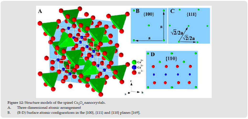
Perovskite and spinel oxides stand out against other transition metal oxide based materials in energy conversion devices designed for ORR, OER and HER, due to the possibility of tailoring their chemical composition and, consequently, their properties. Particularly, the electrocatalytic performance of these materials depends on features such as chemical composition, crystal structure, nanostructure, cation substitution level, e.g. orbital filling or oxygen vacancies. The ABO3 perovskite where A is a rare earth metal on an alkaline earth metal cation and B is a 3d transition metal cation, shows a cubic structure. In this structure A cations and found at the vertices of the cube and B cations are located in am octahedral environment surrounded by 6 oxygen anions that generate BOf octahedron. In the presence of vacancies at the surface, the metal transition orbitals are stabilized adopting a square pyramidal symmetry, where the B cation is surrounded by only o oxygen axions. By octahedra can be also found in spinel-based structures, of general formula AB2O4, which are cubic close-packed anions arrays where cations are occupying tetrahedral and octahedral environments. In the normal spinel A cation occupies tetrahedral sites due to its lower crystal field stabilization energy (CFSE), and B cation occupies octahedral sites due to its higher CFSE. This review provides a brief overview on tenable spinels (mainly cobalt-based/featuring Ni and Li metal cations on octahedral sites, which are known to be active for the electrochemical energy conversion. Among the numerous low-cost non-precious metal oxides, cobalt oxides (spinel cobaltite oxides) are promising for both ORR and OER in alkaline media [160-165]. Co3O4 has a normal spinel crystal structure (A2+B3+2O2-4) based on a close-packed face centered cubic configuration of oxygen ions, as stated at the beginning of this section. CO2+ ions occupy one-eighth of the tetrahedral A sites while CO3+ ions occupy one half of the octahedral B sites [166].
In general, traditional theory states that the ORR is assumed to take place at active sites associated with the cations at the higher oxidation state [166]. During the ORR, the CO3+ ions would act as donor-acceptor reduction sites, due to the ability of Co3O4 to capture electrons and to provide electrons to O2 in solution [167]. It has been reported [168] that the surface Co3- cations on the cobalt oxide electrode can produce surface electronic states by the Jahn-Teller effect (a geometric distortion of a non-linear molecular system, typically observed among octahedral complexes that reduces its symmetry and energy), which essentially states that in this particular situation, these surface states can capture electrons from the bulk oxide to form excited cationic states [Co3+ + e], which can act as the active sites for the alkaline ORR. Therefore, the ORR activity is believed to be directly related to the distribution of Co3+ cations among the different coordination sites at the cobalt oxide surface. Xu, et al. [167] showed that ORR catalytic activity is sensitive to the number of surface exposed Co3+ ions, and the number of sites can be tailored by the morphology of cobalt oxides. Their Co3O4 nano-rod structure exhibits a higher activity than the noble Pd catalyst does at the low potential region. However, their experimental support for the higher density of Co3+ ions on the surface of the sample with the best performance than others was a very slight shift of the Co3+/Co4- redox couple in the CV curve, which can be influenced by various operation parameters between samples. Therefore, the less sharp contrast between the all of the nano-rod samples made the conclusion less convincing. Another theory for the ORR mechanism on Co3O4 was proposed by Xiao, et al. [169] by controllable synthesis of Co3O4 nanorods (NR), nanocubes (NC) and nano-octahedrons (OC) with the different exposed nanocrystalline surfaces ({110},{100}, and {111}, respectively), which have different distributions of Co2+and Co3+, as shown in Figure 12. The Co3+ cations are present solely on the {110} plane, as shown by surface differential diffraction study [170,171]. Similarly, the crystalline phases, morphology and exposed facets were confirmed by XRD, TEM and high-resolution TEM. Shape-dependent ORR catalytic activity of the Co3O4 nanocrystals was clear that both the onset and half-wave potential of ORR on Co3O4 NC and OC were close to each other (OC is slightly higher than NC), about 0.08 V higher than that of Co3O4 NR. The theory behind this phenomenon is that the O2 adsorption/desorption process takes place in a Pauling configuration (Co...(Oads =O)), as opposed to Griffths and Bridge-type modes [172] which is involved in the rate- determining step as suggested by the mismatch of the bond angle on the surface and the bulk and also the bond length of the oxygen molecule and adjacent active sites. Therefore, the surface Co2+ (3d54s2) tends to be the active site rather than the surface Co3+(3d54s1) cations because Co2+ can transfer electrons to the absorbed O2 molecules to weaken and to assist breaking the O-O bond, meanwhile being oxidized to Co3+. This can also partially explain why CoO supported on nitrogen doped carbon nanotubes outperforms its counter part Co3O4 in the same structure in ORR in Liang et al.'s work [173-175]. Further discussion will be provided in the next subsection.
Figure 12
In terms of OER studies with Co3O4 electrocatalysts, the water oxidation activity is generally ascribed to the presence of Co4+ which appeared from the CoO2/CoOOH redox reaction right before the onset of the OER [153,176]. This finding was experimentally supported by Yeo et al.'s work [177] where the OER turnover frequency of cobalt oxide deposited on Au was 40 times higher than that of bulk cobalt oxide by increasing the population of Co4+ due to the electronegativity of gold where the activity decreased monotonically in the order Au > Pt > Pd > Cu > Co, paralleling the decreasing electronegativity of the substrate metal. Their conclusions were joined later by Lu et al. through the OER catalyst of gold nanoparticles incorporated in mesoporous cobalt oxides (Au/m Co3O4) [178]. DFT calculations have also shown that O binds more strongly to a monolayer of Co deposited on Au than to pure Co alone [179]. It is proposed [177,180] that cations with higher oxidation state, Co4+ cations in this particular case, can enhance the electrophilicity of the adsorbed O and further facilitate the formation of O-OH via nucleophilic attack by an incoming OH anion with an O atom associated with Co4+, which is also beneficial for the deprotonation of the OOH species, via an electron- withdrawing inductive effect, to form O2. These two steps are normally considered the rate-determining steps for OER on metal oxides, stated at the beginning of this section. Based on the analysis above, the fundamentally different RDS for ORR and OER on cobalt oxides require totally different catalytically active sites on the catalyst surface. Therefore, the ORR/OER activity can be manipulated by the distribution and exposure of corresponding active sites on the surface through synthesis conditions.
Nickel Cobalt Oxides
It is well understood that NiCo2O4 is a low temperature metastable phase, which appears only below ca 400ºC in air. In contrast to the normal spinel structure Co2+ [Co3+Co3+]O42- of Co3O4, NiCo2O4 has an inverse spinel structure. A number of charge and site distribution models have been proposed. For example, an ionic configuration formula was presented as Cox2+ Co1-x3+ [Ni1-x2+ Ni1-x3+ Co3+]O42- by Lenglet, et al. [181]. But it is well agreed that NiCo2O4 phase has the best ORR activity among all the nickel doped cobalt oxides [182]. Manivasakan et al. have recently successfully synthesized a series of urchin-like mesoporous three-dimensional hierarchical nanostructures of NixCo3-xO4 [183] to comprehensively develop the relationship between the ORR electro-catalytic activity properties of NixCo3-xO4 and its structure, morphology and composition. Among which NiCo2O4 was found to possess the highest surface area (123m2 g-1) and also a significantly improved onset potential and current density for ORR compared with previously reported nickel cobalt oxide structures. The mechanism behind the improved ORR activity was claimed that the improved textural features of NiCo2O4 could provide sufficient exposed Ni3+ and Co3+ species on the octahedral site to produce more surface electronic states in alkaline media, which is consistent to the surface cation distribution theory and Jahn-Teller effect mentioned above [183].
Other morphologies of nickel cobalt oxide were also produced as bifunctional ORR/OER electrocatalysts [182,184,185] such as porous hollow nickel cobalt oxide tubes with the diameter of 100 nm supported on pure acetylene carbon black as an effective bifunctional catalyst for rechargeable Li-O2 batteries [186]. Mesoporous NiCo2O4 nanoflakes grown on a three-dimensional (3-D) porous nickel foam as a decoupled OER catalyst in hybrid lithium-air batteries for the systematic study of how the air electrode configurations affect performance of cells with the same catalysts [187]. The reason that NiCo2O4 has better OER catalytic ability than NiO is proposed by Rasiyah, et al. [188] that transition between valence states of cobalt generally occurs at lower potential than the corresponding transition of nickel, therefore, the onset potential for OER on NiCo2O4 is lower [189].
Lithium Cobalt Oxides
Among numerous cobalt-based binary oxides, LiCoO2 has been among the most studied because of its possible application as a cathode material for lithium-ion batteries. The LiCoO2 with a lithiated spinel structure {Li2}16c[Co2]16dO4 (the Co3+ ions occupying all the 16d octahedral sites and the Li+ ions occupying all the 16c octahedral sites of the spinel framework, space group: Fd3m) can be synthesized at a relatively low temperature (400°C). This spinel structured LiCoO2 has also been applied as an OER catalyst by Maiyalagan et al. [190] and showed higher OER activity than LiCoO2 with a layered NaFeO2 structure (space group: ) synthesized at high temperatures (800°C). It was also shown that chemically delithiated Li1-xCoO2 (achieved by extracting lithium with NO2 BF4 in acetonitrile) possessed high ORR activity, making the spinel-type Li0.5CoO2 a potential bifunctional electrocatalyst for rechargeable metal-air batteries. Other authors have attributed the activities of the delithiated cobalt oxide to the presence of Co4O4 cubane subunits, and a pinning of the Co3+/4+: 3d energy with the top of the O2-: 2p band facilitating the formation of O-O bonds easily leading to an easier release of oxygen [191,192]. However, the OER onset potential is still 0.1 V lower than IrO2 and durability when screened at 1.7 V for only 5 hours, raises doubts whether the oxygen rich structure can be a durable bifunctional catalyst, especially for OER. In the case when lithium exists as a dopant in cobalt oxide, Wu et al. achieved the best OER performance with Li0.21Co2.79O4 synthesized through a nitrate assisted thermal decomposition method. Their cell achieved a high current density at a voltage of 2.05 V at temperatures of 45°C in a single non-precious metal alkaline anion exchange membrane water electrolyser [193].
Due to the changes in cation distribution ((Co2+1)A(Co3+2)BO4 for Co3O4 and (Li+0.21Co2+0.58Co3+0.21)A (Co3+2)BO4 for Li0.21Co2.79O4, electronic conductivity: 2.1±0.2 S cm-1) and variation in binding energy of surface oxygen. The doped cobaltite oxide has better OER activity due to the better electronic conductivity and cation distribution, as compared by Nikolov and co-workers, where the electrochemical behaviours of binary cobalt oxide MXCo3-XO4 (M = Li, Ni, Cu) were compared and it was found that the activity of the spinels increased in the order Co3O4 < NixCo3-xO4 CuxCo3-xO4 < LixCo3-xO4 [194]. The stability of Li0.21Co2.79O4 was examined under continuous operation for 10 h at above 2 V and at 30°C. The author chose a higher voltage to justify the durability of the doped cobaltite than most of other reports, however, a voltage increase of more than 0.2 V only in the first 10 hours was not a very excellent starting performance for electrolyzers, and there is also stability improvement potential for membrane and ionomers in alkaline water electrolyzers.
Other cobalt oxides such as CuxC3-xO4 and MnxC3-xO4, whose complex structures and cationic distributions (Co3+[Mn2+Co3+]O4 [195-198], Co2+ [Mnx3+Co2-x3+]O4 [199- 202], or Co2+[Mn4+Co2+]O4 [203], etc.) have been numerously proposed in literature due to the multivalence of Mn ion depending on the preparation method and the calcination temperature, have also been proposed as an attractive non-precious oxygen electrocatalyst for oxygen reactions [204]. Some examples as reversible ORR/OER catalysts would be further discussed below in the next subsection. Although mixed transition metal oxides have shown some promise as ORR, OER and reversible ORR/OER electrocatalysts after some modification, their performance is essentially always limited as direct electrocatalysts in fuel cell applications by their low electrical conductivity. Therefore, the introduction of support materials with high electronic conductivity is almost always needed in order to not only increase conductivity, but also enhance their dispersion and often their durability.
Impact of the Support on ORR Electrocatalysts
As mentioned above, regardless of the electrolyte, platinum group metals remain the most common oxygen electrocatalysts. One method to reducing the amount of Pt used at these electrodes, in order to reduce cost, is to increase dispersion through the use of a support. Carbon is the most common support for Pt in modern systems; however, the conventional Pt/C catalytic mass activity still requires a factor of > 4 increase for the significant cost of large-scale applications [205]. Although the efforts of developing advanced carbon support materials to improve the stability and electrocatalytic activity of Pt clusters have improved device durability over time, the long-term instability of carbon materials still remains a major concern. The short catalyst life may be first caused by the thermodynamic limitations of carbon support itself due to the oxidation/corrosion, as shown in the electrochemical reaction in equation 22 [206,207]:

The surface carbon atoms can be activated electrochemically at any potential above 0.207 V vs. the normal hydrogen electrode (NHE). This means that carbon supports are intrinsically unstable under normal fuel cell operating conditions (0.6 < Ecathode V < 0.8; 60 <T(°C) <90) Then, the activated carbon species become the final product of Co2 when reacting with neighboring water molecules, which then leads to mechanical failure and collapse of the catalyst layer pore structure. What's worse, the supported Pt may act as a catalyst for the carbon oxidation [208], which may localize the corrosion to areas in direct contact with Pt. This would further cause the poor dispersion or even the dissolution of Pt clusters on carbon. Other than the long-term stability issue of the catalyst itself, there would also be membrane degradation induced by the relatively high activity of carbon towards the two-electron reduction of oxygen to hydrogen peroxide [209,210]. Therefore, it is still a major challenge to design cheap and stable electrocatalysts for ORR in fuel cells. A large number of alternative ceramic support materials have been introduced in the literature to manipulate the Pt dispersion, size, shape, etc. through electron transfer between the catalyst and support, and further improve corrosion resistance and reduce electrochemical surface area (ECSA) degradation rates [211-216]. Metal-support interactions can also improve the electrocatalytic activity of the supported Pt in several ways such as modification of the electronic states of Pt to increase the potential of the formation of Pt-OH groups [217] and reduction of the equilibrium OH adsorption by lateral repulsion between Pt-OH and oxide surface [218,219]. Therefore, several studies and reporting ways to produce the potential modified ceramic support for platinum in acidic media [220-223], as well as other studies report the application of tin-doped indium oxide (ITO) as an electrocatalyst support for Pt in alkaline media explored [224-226]. The ORR activity and stability of Pt/ITO are compared with a commercial Pt/Vulcan electrocatalyst. The differences of Pt/ITO catalyst in acidic and alkaline media, and the possible reasons for its high activity and stability are discussed.
In-Situ vs. Ex-Situ Synthesis Processes
In this section, carbon-catalyst hybrid materials with an inorganic component attached to the outer surface of CNTs, instead of filling CNTs, will be discussed. These structures maintain the conductive CNT inner layers while resulting in highly functionalized outer layers as the active sites for both oxygen reactions. These CNT- inorganic hybrids can be realized by various synthesis strategies, which can be categorized as ex-situ and in-situ techniques. The ex-situ approach first produces the inorganic component in isolation, possessing the desired dimensions and morphology. Then, the surface is modified and the inorganic is attached to the surface of the CNTs via a second process, such as covalent, noncovalent, or electrostatic interactions. Simply put, the formation of the inorganic components and the combination with the support are two independent steps [227,228]. On the contrary, in-situ approaches carry out the synthesis of the inorganic component in the presence of pristine or functionalized CNTs, onto which the inorganic material is grown as particles, nanowires, or thin films [229]. Ex-situ processes tend to have weaker bonding between the inorganic components and the supports, which may not be good for long-term catalyst stability, particularly for the OER where a very harsh oxidizing condition exists as well as mechanical issues brought on by constant gas evolution from the catalyst surface. These structures may be more feasible in ORR-only systems where physical blends of graphene-like carbon and - Ni-a-MnO2 and-Cu-a-MnO2 have already been demonstrated with comparable activities to Pt/C and reasonable durability [230,231]. Additionally, Guo et al. synthesized monodisperse Co/CoO nanoparticles (NPs) and deposited them ex-situ onto a graphene (G) support through solution-phase self-assembly, and the resulting G-Co/CoO exhibits a comparative activity and better stability than the commercial C-Pt NPs in KOH (0.1 M) electrolyte [174].
Treatment of Advanced Carbon Materials
To enhance the bonding between support and metal oxides, a chemical bond is often introduced between the two, which is more feasible using in-situ, methods. In order to grow transition metal oxides onto CNTs, forming covalent bonds between the oxides and supports to promote adhesion, the CNTs must be functionalized initially to provide enough anchoring sites for the metal oxides. One of the most convenient and energy- saving ways to introduce oxygen functional groups to carbon materials is chemical oxidation, which is typically achieved by using concentrated acids or bases, oxidants such as hydrogen peroxide and potassium permanganate, or the combination of both [232-234]. Various oxygen functional groups are introduced during this process including carboxyls, carboxylic anhydrides, and lactones, as well as aldehydes, ethers, hydroxyl groups exhibiting phenolic character, and carbonyl groups such as quinones or pyrones [235-237]. Datsyuk et al. measured the oxidation degree of multi-walled CNTs treated by different oxidation agents through Raman spectroscopy and X-ray photoelectron spectroscopy [232]. They concluded that the increase of the degree of surface oxidation follows the trend of hydrochloric acid < ammonium hydroxide/hydrogen peroxide < piranha < refluxed nitric acid. Oxidative treatment, with the exception of nitric acid, did not lead to the production of additional defects on the outer walls of the multi-walled CNTs. Therefore, the oxidants can be used to serve the purpose of introducing more anchoring sites for metal oxide growth were narrowed down to nitric acid and potassium permanganate [234]. More experimental details of the influence of different oxidants an provided in references [232-238]. Pre-treated advanced carbon can be used as direct substrate for metal precursors to react on in various synthesis methods, which will be discussed below.
Hydrolysis in Alcohol-Water System/Hydrothermal Reaction
Dai et al. developed a two-step procedure to synthesize metal hydroxides and oxides on graphene oxides (GO) or oxidized CNTs. This method basically includes a hydrolysis of metal precursor salts selectively on oxidized carbon as the first step with a secondary step of either hydrothermal/solvothermal treatment or thermal annealing in the gas phase to convert the coating into crystalline metal hydroxides or oxides [239]. In the first step, metal ions are added to GO in solution to interact with oxygen functional groups on GO and adsorb onto these groups. At these adsorbed sites, hydrolysis of metal ions is initiated to nucleate and grow metal hydroxides or oxides. Nucleation and growth could also take place in free solution, which would compete with selective nanoparticle nucleation and growth on GO and is undesired. Their work found that there are several important parameters to control the competition over free growth in solution, such as the usage of a mixture of solvents and reaction temperature control. Various additives, such as ammonia and other complex compounds, could affect the reaction rate as well. The annealing temperature and atmosphere in the following thermal treatment step can impact the phase, size and morphology of the materials grown on GO. Hybrid materials of various nanocrystals and nanoparticles with nano-carbon materials were developed by this method for several electrochemical and photocatalytic applications such as supercapacitors, batteries, electrolyzers and fuel cells. Among these materials, good candidates for bifunctional ORR/OER catalysts have been attained. Strongly coupled Co3O4-N-mrGO (nitrogen doped mildly reduced graphene oxide) hybrid synthesized from the above two-step method exhibited great performance towards both ORR and OER reactions in KOH solutions, indicating the potential to be good non- precious metal bifunctional candidate [240]. This hybrid catalyst exhibited high ORR activity with an onset potential of 0.9 V vs. the reversible hydrogen electrode (RHE) during rotating disk electrode (RDE) measurements, which made it the most active ORR catalysts based on Co3O4. A complete four-electron reduction was shown using Koutecky-Levich plots from 0.60-0.75 V. Different from the proposed ORR active sites of Metal-N species in Fe- or Co-N/C catalysts [241] prepared at much higher temperatures (600-1,000 °C) with lower metal loadings (<1-2 at% of metal), the Co oxide species at the interface with graphene is believed to be the active site for the above high Co loading Co3O4-graphene hybrid catalyst, obtained at lower synthesis temperature. Also, the much improved ORR activity than raw Co3O4 catalyst was analyzed through the synergistic effect between Co3O4 and the N-mrGO by the possible formation of interfacial Co-O-C and Co-N-C bonds via X-ray absorption near edge structure measurements. A higher electron density at the O site and a lower electron density at the Co site consequently suggested a higher ionic Co-O bonding in the hybrid.
The ORR activity was further improved by substituting half of the Co3+ in the spinel structure of Co3O4 with Mn3+ due to an increase in electron density [154]. But when the Mn/Co ratio is larger than one, the ORR activity started to decrease due to a phase transition from a cubic spinel to a tetragonal spinel phase [242], which possesses a lower intrinsic ORR activity than the cubic phase [114]. Similar cobalt oxide based hybrid structure with other advanced carbon material support such as mildly oxidized multiwalled carbon nanotubes (CNTs), synthesized via modified procedure showed further improved properties [173]. The half-wave potential in the linear sweep voltagram of Co3O4 supported on nitrogen doped CNT (NCNT) was similar to Co3O4/N-rmGO), about 35 mV more negative than Pt/C catalyst. Also, when the second hydrothermal step was replaced by a thermal annealing at 400°C in a NH3/Ar atmosphere, the peak voltammetric current density on the obtained CoO/NCNT catalyst was increased by ~30%. In a setting that is more similar to a practical fuel cell operation, the authors loaded catalysts on Teflon-coated carbon fiber paper, where CoO/NCNT exhibited significantly higher ORR current than the Co3O4/N-rmGO hybrid, possibly due to a higher electrical conductivity, which can be observed in electrochemical impedance spectroscopy measurements in the ORR region at 0.8 V for various catalysts. The OER electrocatalytic activities of the above Co3O4/N-rmGO hybrids was similar to that of the Co3O4 and graphene physical mixture, indicating that a strong coupling between Co3O4 and graphene is particularly important for ORR, though less critical for OER [243]. And the MnCo2O4/N-rmGO hybrid exhibited lower OER currents than Co3O4/N-rmGO due to the reduction of Co3+ OER active sites (Co3+ / Co4+ transition) with Mn3+ substitution, but still higher than physical mixture. Therefore, these hybrid structures can be considered as reversible ORR/OER candidates.
Ning et al. achieved highly active and stable hybrid spinel CuCo2O4 nanoparticle electrocatalysts supported on N-doped reduced graphene oxide (N-rGO) using a similar solvothermal method [244]. The introduced Cu2+ ions have excess octahedral stabilization energy and should preferentially occupy the octahedral sites of the spinel structure. They increase the lattice parameter due to a larger ionic radius in the octahedral coordination (0.73 Å) than that of Co3+ ions (0.55 Å for low spin and 0.61 Å for high spin). The ORR onset potential for Co3O4/N-rGO hybrid is ~30 mV more positive than that of the CuCo2O4 /N-rGO. Singh et al proposed a similar approach to synthesize Co3O4 supported on N-doped graphene with preferential exposure of low surface energy facets, which showed a low overpotential (~280 mV) for OER at a current density of 10 mAcm-2 [245]. Gong et al. synthesized and analyzed a highly OER active phase - nickel-iron layered double hydroxide (NiFe-LDH) nanoplates, which can be used as a novel electrocatalyst material. When grown on mildly oxidized multiwalled carbon nanotubes (CNTs), the NiFe-LDH/CNT hybrid exhibits even higher electrocatalytic activity and stability for OER than commercial precious metal Ir catalysts in alkaline solutions due to an electron transfer enhancement [246,247]. The synergistic effect between NiO alone and graphene support was explained by the pinning effect of hydroxyl/epoxy groups on the Ni atoms of NiO based on first-principles calculations in Zhou et al.'s work. Wang et al. synthesized NiO nanoparticles supported on metal-nitrogen-carbon sheet to achieve improved OER performance via the synergistic effect between the NiO and the support materials. Before they grew inorganic metal oxides, they further functionalized the nitrogen doped graphene oxide with transition metals such as Co and Fe with the aid of polymers to achieve Fe-nitrogen-carbon (FeNC) and Co-nitrogen-carbon (CoNC) sheets, respectively, in order to further increase the active sites for OER [248-250].
Chemical (Polyol) Reduction Process
Chemical reduction is typically a one-pot solvothermal strategy using metal acetate or nitrate as metal precursors and desired advanced carbon materials in polyols, which serves as the dispersing agent as well as the reducing agent. Traces of ammonia and thiourea are sometimes added to produce nitrogen and sulfur functional groups on the carbon support to create better anchoring sites or chalcogenides at the same time.
Zhang et al. synthesized strongly coupled NiCo2O4 supported on reduced graphene oxide nanosheets through a polyol reduction route, showing an ORR onset potential of 72 mV more negative than that of the commercial 20 wt% Pt/C catalyst. The metal ions were reduced to nucleate on abundant functional groups on GO by refluxing in ethylene glycol at elevated temperature [251]. After generating a uniform layer of Ni-Co- glycolate conformally coated on both sides of the GO sheets, high-temperature annealing was carried out in air to further achieve NiCo2O4 nanocrystals on the surface [155]. Liu et al. used a similar ethylene glycol reduction method to achieve the novel hybrid of NiCo2S4 nanoparticles grown on graphene in situ. This NiCo2S4 supported on N/S double-doped reduced graphene oxide material is described as an effective bifunctional nonprecious electrocatalyst. It has much better durability for alkaline ORR in comparison with commercial Pt/C catalyst with a 0.08 V reduction of onset potential but better methanol tolerance ability as well as promising OER performance in both neutral and basic media [252]. Yan et al. obtained cuprous oxide (Cu₂O) nanoparticles dispersed on reduced graphene oxide (RGO) using diethylene glycol as both solvent and reducing agent [253]. The Cu2O/RGO exhibits the same onset potential, 0.05 V more negative half-wave potential when compared with commercial Pt/C, as well as remarkable tolerance to methanol and CO during the ORR. Except the two major solvothermal based methods mentioned above, many other novel and non-mainstream synthesis routes have been proposed in literature to produce advanced carbon-based transition metal oxide hybrid structure for oxygen reduction and evolution reactions. Mao et al. designed and fabricated hollow crumpled-graphene with supported CoO nanohybrids (CG-COO) through a one-step aerosolization approach. In this aerosolization/high-temperature-induction procedure, the suspension containing GO with precursor ions (Co2+) was nebulized to generate micro-size aerosol droplets that flowed through a tube furnace at elevated temperature. The rapid evaporation of the solvents in the tube led to a shrinkage of GO sheets and the subsequent compression the GO sheets into crumpled balls with a submicrometer size. Simultaneously, CoO nanocrystals assembled on both external and internal surfaces of the CG balls during the solvent evaporation and the GO crumpling process [254]. This three-dimensional structure exhibited much more stable performance as bi-functional catalysts for both ORR and OER in alkaline solutions compared with conventional two-dimensional graphene. This was due to the prevention of active surface area loss caused by natural restacking of graphene sheets. Electrodepostion is another approach adopted by researchers as the initial synthesis step. Zhang, et al. [255] and Wang, et al. [256] decorated graphene with Fe2O3 nanoclusters and carbon paper with flower-like 3D MnO2 ultrathin nanosheets, respectively, as an O₂ electrode for high energy rechargeable Li-O₂ batteries using an electrochemical approach in iron and sodium salt electrolyte. Many of these hybrids structures discussed above exhibited superior performance than their Pt/C catalyst benchmark in alkaline solution. The improved ORR/OER activities were summarized into a few groups:
Therefore, a thorough discussion on and investigation into stability is still a critical need. In fact, durability, not activity, is often the primary driver for industrial adoption in these systems, though, of course, a combination of both stability and durability is desired. In references [257-263], the durability issue of the carbon-based hybrid material as bifunctional catalyst in alkaline media is further explored. References [264-273] on the topics studied are also recommended for interested readers.
The literature review is a contribution towards creating engineering devices that could link together the fields of hydrogen storage technology, fuel-cell technology and battery technology. The research study also aims to contribute to the current body of knowledge on the science of materials by describing and characterizing novel composite materials that are capable of conducting both protons and electrons simultaneously. Selected low-cost materials may be used together with solid polymer electrolyte membranes (PEMs/AEMs) in unitized regenerative fuel cells (URFCs), and their capacity for electrochemically storing and discharging hydrogen in acidic and alkaline media has been investigated. Moring on further details, the analysed questions addressed in this paper are as follows:
• Role of hydrogen in a sustainable energy strategy;
• Hydrogen storage technologies;
• Electrochemical storage of hydrogen in activated carbon;
• The proton flow battery concept with ac electrode;
• PEM electrolyzers;
• Methods of hydrogen storage;
• PEM fuel cells;
• Structure and principles of a PEM URFC;
• A hydrogen system employing an electrolyzer, storage unit,
and fuel cell;
• A hydrogen system employing a URFC and storage unit;
• Integrated carbon hydrogen storage in a reversible URFC;
• Mechanism of ORR in acidic electrolyte;
• Mechanism of OER in acidic electrolyte;
• Possible advantages of alkaline electrolyte oven acidic
electrolyte;
• Transition mental oxide electrocatalysts;
• Cobalt-based spinel oxides;
• Nickel cobalt oxides;
• Lithium cobalt oxides;
• Advanced carbon-based hybrid materials;
• Impact of the support on ORR electrocatalysts;
• In-situ vs. ex-situ synthesis processus;
• Treatment of advanced carbon materials;
• Hydrolysis in alcohol-water system/hydrothermal reaction;
• Chemical (polyol) reduction process.
As it can be concluded the former part of this study investigated the role of hydrogen in a sustainable energy strategy, and the concept of a reversible URFC with an integrated carbon hydrogen storage electrode. Then transition metal oxides were investigated as support materials for electrochemical catalysis, with a primary focus on oxygen reduction and evolution, in devices such as PMFCs, PEMFCs, AFCs and alkaline URFCs. Based on all the directions focused above, the following recommendations can be extended:
1. It will be useful in future research to conduct computer modelling to investigate movement of protons in the pore structure of activated carbons and to check to what extend H3O+, H5O2+ and H9O4+ ions enter ultra-micropores. Moreover, Molecular Dynamics modelling may be appropriate in discovering their movement.
2. Establish novel preparation techniques for disordered types of carbon natural to be used in reversible and direct hydrogen storage.
3. Improve the performance of composite materials of carbon and proton conducting media in different levels of hydration.
4. Select proper procedures to fabricate activated carbon samples, the composite materials and the composite electrodes for URFCs.
5. Incorporate the fabricated composite electrodes into URFCs for direct reversible hydrogen storage.
6. Establish how does the performance of the URFCs with composite electrodes compare with that of typical standard URFCs.
7. Try to understand the doping density quantitatively and its influence on oxygen electrocatalysis with new methods and models, such as Mott-Schottky (MS) analysis. Acquisition of MS plots is a manual way for semiconductor materials electrochemical characterization.
8. Defining the active sites for both ORR and OER on mixed valence metal oxide by systematic experimental configuration.
9. Understanding the in-situ phase transition, electronic structure modification, such as the d-band center or Fermi level changing, which can be realized by creating an in-situ FTIR and conductivity test in the rotating disk electrode (RDE) electrochemical test.
10. Optimizing parameters in the procedure with CNT-based hybrid catalysts for reversible alkaline fuel cells, such as oxidizing conditions, precursor substitution, CNT size, post-treatment, etc., eventually to scale up the novel materials to test in unitized regenerative fuel cells.


 Abstract
 PDF
PDF